Category Archives: FPC - Page 3

Flexible circuit substrate thickness

This time let’s to see the several kinds of based flexible circuit substrate thickness, & then you can see which is the best suitable for you.

1. Coverlayer of flexible circuits:

1). 12.5um: PI:12.5um; adhesive:15um; total thickness: 27.5um
            PI:12.5um; adhesive:25um; total thickness: 37.5um
2). 25um:   PI: 25um;  adhesive:25um; total thickness: 50um

2. Substrate thickness of flex circuits

1).Single RA copper:

18/12.5UM: copper thickness:18um; PI:12.5um;adhesive:13um; total thickness 43.5um
35/25UM:  copper thickness:35um; PI:25um; adhesive: 20um; total thickness 80um

2).Double-sided RA copper:

18/12.5UM: copper thickness:18um; PI:12.5um; adhesive: 13um; total thickness: 74.5um
35/25UM: copper thickness:35um; PI:25um; adhesive: 20um; total thickness: 135um

I think we have all of your required thickness, we haven’t any problem to product it according to your requirements. OK, if you need further information of flexible circuits(flex pcb), please contact us feel free.

Flexible Circuits Price

Almost all the electronics factory purchasement staff have been confused about the changing price of flexible circuits, even if some have many years of experience in the purchasement of flexible circuits  staff has not totally understand the causes. In fact, the price of flexible circuit board by the following multi- factors:

1, flexible circuit boards of the multifarious price caused by different material;
2, flexible circuit boards used in the different production process caused by the multifarious price;
3, the difficulty of flexible circuit board itself caused the multifarious price;
4, customer different requirements will result in different prices;
5, different flexible circuit board manufacturers will course multifarious price;
6, different method of payment of price will course multifarious price;
7, different regional also will course multifarious price.

You can see the above main seven factors consist of flexible circuit boards price. If you have an inquiry about the flexible circuit boards, please don’t hesitate to contact us, we will offer you the very competitive price.

Flexible Circuits Production Process

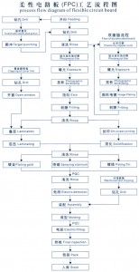
Last time we talk about the PCB production process, now please see the below form of flexible circuits production process for you study.

CMD Circuits has a very strict quality control system to ensure to make high quality flexible circuits. Please feel free to contact us for any queries.

the whole thickness of FPCs

Now I want to introduce the wholes thickness of FPCs. As is known to all, there are four kinds of FPCs(flexible circuits): single-sided FPC, double-sided FPC, dual access FPC and multiayer FPC. Let’s see the thickness of single-sided and double-sided FPC as examples:

(!) single-sided FPC

The constructure of single layer FPC is as follows:

25um+20um+35um+20um+25um=125um≈0.12mm

Note: the thickness of adhesive changes according to the thickness of Cu. For 1/2, 1/3 OZ Cu, we usually use 12um adhesive. But for 1OZ Cu, we have to use 20um adhesive.

That’s according to the common material. If we want the board to be thinner, we also can use the adhesiveless material to make the board about 0.60mm thick.

(2) double-sided FPC

Double sided FPC means there are two layer of traces in the FPC.

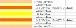
The constructure of double sided FPC is as follows:

25+12+35+12+25+12+35+12+25=193um≈0.20mm

Now you have an idea about the whole thickness of the FPCs, if you need more information, please contact us anytime.

Copper foil features of flexible circuits

Here, let’s to know the more details of copper foil is used in the flexible circuits. The cooper foil is very improtant part of flexible circuits.

1. There are two kinds of copper foil:
1>. rolled annealed copper foil(RA-copper)
2>. electrodeposited cooper foil(ED-copper)

2. The thickness:
1>. normally use 1/3oz, 1/2oz,1oz and 2oz four kinds;
2>. RA-copper: 1oz, 1/2oz, 1/3 oz or less thickness, but higher cost.

3. flexibility:
Rolled annealed copper foil is of high strength and can stand bending, two times for electrodeposited cooper.

Now, I think you know the Copper foil features of circuit boards more details. Ok, if you need more information, please do feel free to contact us.

Flexible Circuits Applications

Flexible circuits can be used in many applications as the benefits of flexible circuits in many industries.

Highly automated fabrication methods, these ways can reduce workers handling of the flex circuits, reducing both cost and probability of error. Applications like cameras, printers, disk drives, and automotive panels.

High accuracy circuits is to handle ultra-fine lines and tight tolerances in an age of miniaturization. Such as used in aerospace and medical applications. Flexible circuits applications are most used in many industries including:

·Personal and mainframe computers, disk drives, and printers
·Automotive radios, cassette players, electronic control systems and on-board computers
·Telecommunications equipment, telephone handsets, and switching systems
·Consumer electronics like calculators, stereos, cameras, and compact disk players
·Heart pacemakers, hearing aids, and other medical applications.
·Jet engines, navigational and flight control systems
·Industrial controls, machine tool controls, and robotics

What types of flexible circuits are available?

There are four basic types of flexible circuits(FPC) are available. These four types of flexible circuits can be used in different combinations to solve most every interconnection design problem.

1. The simplest flexible circuit is single-sided FPC. They provide maximum flexibility for dynamic applications and can withstand hundreds of millions of flex cycles. These simple circuits are also the most easily adaptable to SMT, TAB, and other developments in circuit technology.

2. Double-sided FPC consists of double-sided copper clad material with top and bottom cover films. The ability to interconnect between sides using through-hole plating helps double-sided circuits carry complex designs, and still maintain flexibility.

3. Multilayer FPC are ideal for complex, highly populated design requirements. Large numbers of conductors can be designed into a small package. Maybe flexibility will be somewhat limited by the number of layers in the design. Multilayer circuits are also the ideal problem-solving technology when confronted with design challenges like unavoidable crossovers, specific impedance requirements, elimination of crosstalk in sensitive circuits, additional shielding or ground planes, and high component density.

4. Rigid-Flex circuits are circuits combination of Rigid circuit and Flex circuits. So it have both the advantage of each other and it’s newest types used in various applications.

For more information of the flexible circuits, please do feel free to contact us.

What are the benefits of using flexible circuits?

What are the benefits of using flexible circuits? Flexible circuits provide below major benefits over rigid circuit boards.

1>. A solution to a package problem;
2>. Reduce assembly costs
3>. Replacement for a circuit board and wires;
4>. Reduce weight and space;
5>. Dynamic Flexing;
6>. Thermal management/high temperature applications;
7>. Aesthetics.

So most designers choice the flexible circuits for most applications.

The performances of flexible circuits

This time let’s to know the performances of flexible circuits.

(1) Base material:
PI(Polyimide) is the most common used, which is a kind of macromolecule material of high temperature proof and high strength, invented by Dupont. The polyimide made by Dupont is called Kapton. Besides some polyimide made in Japan can also be found. Its price is much lower. Polyimide can bear 10 seconds of high temperature of 400 degree centigrade. Its tensile strength is 15,000~30,000 PSI. The base material with 25um thickness is the cheapest and the most popular one. If we need the circuit board to be more rigid, we should choose 50um. Otherwise, if we need the circuit boards to be more flexible, then choose 13um.

(2) Adhesive:
It is divided into epoxy resin and polyethylene, they are all thermosetting adhesive. The polyethylene’s strength is lower. If we hope the circuit boards to be more flexible, then choose polyethylene. The thicker the base material and the adhesiveon it is , the more rigid the circuit boards are. If the circuit boards have to be bent in a large area, we should choose thinner base material and adhesive so as to reduce the stress on the surface of the copper, then lower appearance of micro crack.

(3) Copper:
It is divided into rolled annealed copper foil and electrodeposited cooper foil. Rolled annealed copper foil is of high strength and can stand bending, but its price is higher. Electrodeposited copper foil is much cheaper, but of low strength, easier to be bent.

When we choose to use rolled annealed copper foil, we should pay attention to the direction of the copper. The direction of the copper has to be the same with the bending direction of the circuit boards.

(4) Coverlay with adhesive:
25um coverlay would make the circuit board more rigid, but it is cheaper. Therefore to the circuit board needing to be bent greatly, we’d better choose 13um coverlay.

The adhesive is also divided into epoxy resin and polyethylene. The FPC using epoxy is more rigid. After thermosetting, there are some adhesive squeezed out at the edge of the coverlay. If the soldering pads are larger than the hole on the coverlay, the adhesive squeeze out would reduce the size of the soldering pads and lead to irregular edge. Therefore, we’d better choose 13um adhesive.

These are more details about the performances of the flexible circuits. If you still need more information, please do fell to contact us.
The structure of FPC

This time let’s talk about more details about the structure of FPC(flexible circuits). Normally, according to the layer of conductive copper, FPC is divided into single-sided, double-sided, multilayer, dual access, etc.

The structure of single-sided FPC is the most simple. Based material FCCL: PI + adhesive + copper and adhesive + coverlay top layer. Firstly, the copper needs to be etched to get the traces, while the coverlay needs to be drilled to expose corresponding soldering pad. Make the plating for the exposed soldering pads to protect from oxidization. At last, FPC is punched into corresponding outline by required.

The structure of mulilayer FPC: The most typical difference between multilayer and single layer FPC is that the multilayer FPC is added with plated through holes to connect the copper on every layer. The first workmanship of Based material FCCL: PI + adhesive + copper is to make plated through holes(PTH). Later the technique is almost the same with single layer FPC.

The structure of dual access FPC: dual access FPC has soldering pads on its two sides, mainly used to connect with other circuit boards. Although it has similar structure with single layer FPC, its technique has great difference.

These are the more details of the structure of types of FPC, if you need more information, please don feel free to contact us.

Pages: Prev 1 2 3 4 Next