Author Archives: Frank - Page 2

PCB development trends of advanced manufacturing technology

Summary of domestic and international manufacturing technology for the future development trends of PCB production is basically the same discourse: namely high-density, high precision, small hole diameter, fine wire, fine pitch, high reliability,multi-layered, high-speed transmission, lightweight, thin thickness development, and in production to improve productivity, reduce costs, reduce pollution and meet the many varieties and small batch production direction.
As printed circuit boards level of technological development, we often use the line width, diameter, thickness / diameter ratio as the representative. Please see the level of PCB development process as follows:

Level of development of printed circuit boards technology:

Years
 1970
 1975
 1980
 1985
 1990
 1995
 2000

Aperture (mm)
 1.0
 0.8
 0.6
 0.4
 0.3
 0.15

Width (mm)
 0.25
 0.17
 0.13
 0.10.
 0.08
 0.05

Thickness / aperture ratio
 1.5
 2.5
 5
 10
 20
 40

 Hole density, number of holes / CM2
 4
 7.5
 15
 25
 40
 55

CMD Circuits is engaging in manufacturing the high quality and competitive cost printed circuit boards and flexible pcb for our customers.

Methods of saving PCB cost

In order to let the cost of PCB can be as low as possible, there are many factors that must be taken into account:

1. The size of the board is most important. The smaller board, the lower the cost. Part of the PCB has become the standard size, as long as the cost according to size as it will naturally decrease.
2. SMT will be much lower than THT, because the components on the PCB will be more intensive (also small).
3. On the other hand, if the components on the board is very dense, then the routing must also be more detailed, and the equipments should be correspondingly higher required. The cost of these problems,compare to reduce the PCB size with more savings.
4. The more layers the higher the cost.
5. Drilling takes time, so NTHs the less the better.
6. Buried holes is more expensive than NTHs. Because the buried hole must be drilled at the junction.
7. Hole size.
8. Others.

Last, the equipments in manufacturing is more complicated, the cost will be more high. Understanding of PCB manufacturing process is very useful to save the cost. CMD Circuis have professional working group to analyze and control the cost of material.

Drilling of flexible circuits

Drilling is a flexible circuit an important processing operation, as the flexible circuits material was soft and easy to deformation, It’s different from the rigid printed circuit boards when drilling. The process is as following:

lamination → fixed → drilling → demolition board

lamination: it is going to pile up the copper substrate material or the protective film material together at a certain layers, and at the bottom and top layer with  plate and covered tightly with a single-sided adhesive tape together.

CMD Circuits offer you more information about the flexible circuits here blog.

PCB copy board methods and steps

As you know, sometimes we will face to copy pcb as our customers just have the pcb circuit board samples in hand, no gerberfile. Please see below details of the PCB copy board methods and steps.

The first step, get a piece of PCB, keep records on paper of all molds, parameters, and location of the components, especially direction of diode, three machine and IC gap. Best to use digital camera to take photoes of the locations.

The second step, remove all the components, and remove the tin in PAD hole. Then use alcohol to clean printed circuit board, and then turn into the scanner,start POHTOSHOP, with a color screen to scan the silk screen side, save the file and print out.

The third step, use the water tissue paper to top layer and bottom layer minor sanding, grinding to a shiny copper film, into the scanner, start PHOTOSHOP, two color ways were swept. Note, PCB placed in the scanner must be horizontal level within the tree, otherwise the scanned image will not be able to use, and save the file.

The fourth step is to adjust the contrast of the canvas, with strong conparison between the copper film and no copper film part, then turn second picture to black and white color, check the lines are clear, if not clear, repeat this step. If clear, save the picture into black and white BMP format: TOP.BMP and BOT.BMP, if found in graphics problems can be repaired and modified with PHOTOSHOP.

The fifth step, turn these two files converted to PROTEL format, in PROTEL with two layers, if the PAD and VIA of two layers are on the same plase is means that the first few steps do well, if biased, then repeat the third step.

Sixth, Turn the TOP layer of BMP into TOP.PCB, attention should be transformed to the silk layer, that layer is yellow, and scan the top layer, and place the components according to the second step of the drawings.

Seventh step, turn the BOT layer of BMP into BOT.PCB, attention should be transformed into SILK layer, that layer is yellow, and scan the top layer. Deleted silk layer when finished.

Eighth step, Let TOP.PCB and BOT.PCB together in PROTEL, merged into a graph, it’s OK.

The ninth step, use a laser printer to print TOP LAYER, BOTTOM LAYER to a transparent film on the (1:1 ratio), put the film onto the PCB, compare to them, if right, you’re done .

Other: If it’s a multi-layer pcb, we should repeat the third to the ninth step, of course, named of the graphic is different, based on the number of layers. It’s much simpler to copy multi-layer double-sided pcb than multi-layer pcb.

Ok, these are the ninth steps of the double-sided pcb copy menthods, for more information, please contact us.
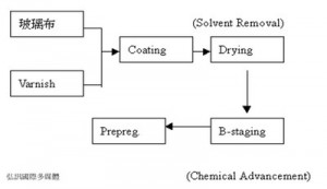
Prereg Making Process

Prereg also named “bonding sheet” (adhesive film), it’s the main part of the pcb substrate CCL, and made by glass fiber or other impregnated resin fibers.

Please see the blow form of prereg making process:

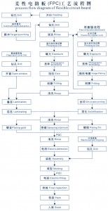
Flexible Circuits Production Process

Last time we talk about the PCB production process, now please see the below form of flexible circuits production process for you study.

CMD Circuits has a very strict quality control system to ensure to make high quality flexible circuits. Please feel free to contact us for any queries.

PCB surface treatments

Bare copper itself is very good solderability, but is easily exposed to air oxidation, and susceptible to contamination. This is also the PCB surface treatment must be the reason.

1. HASL
Hot-air solder leveling. The most common PCB surface treatment menthod. Lead and lead-free should be considered.

2. OSP
Organic solderability protective coating (OSP, Organic solderability preservative) is an organic coating to prevent oxidation of copper in the welding before, that is to protect PCB(printed circuit board) pad solderability from destruction.

3. ENIG
Nickel Immersion Gold. The copper surface is plated of Ni/Au. The deposition thickness of the inner Ni layer is generally 3~6um, the deposition thickness of the outer Au thin, usually 0.05 ~ 0.1um. Ni as the barrier layer between Cu and soldering tin. Welding, outside Au in the solder which melts rapidly with soldering tin and then turn into Ni/Sn intermetallic compounds with inner Ni. The gold-plated to prevent Ni oxidation during storage or passive, it should be enough gold plating density, the thickness can not be too thin.

4. Immersion Silver
Immersion silver process through the thin (about 0.1~0.4um) and dense to provide a layer of silver deposited organic protective film, the surface of the silver with the greatly extended life. Immersion Silver surface is very flat and very good with weldability.

5. Immersion Tin
Only used for two reasons for immersion tin process: first, the surface is very flat, coplanarity good; the other is lead-free. But in the immersion tine process easy to be with Cu/Sn intermetallic compound, Cu / Sn intermetallic is with poor solderability.

These are five main PCB surface treatments, since each have their own unique surface treatment technology, application is not quite the same.

What types of flexible circuits are available?

There are four basic types of flexible circuits(FPC) are available. These four types of flexible circuits can be used in different combinations to solve most every interconnection design problem.

1. The simplest flexible circuit is single-sided FPC. They provide maximum flexibility for dynamic applications and can withstand hundreds of millions of flex cycles. These simple circuits are also the most easily adaptable to SMT, TAB, and other developments in circuit technology.

2. Double-sided FPC consists of double-sided copper clad material with top and bottom cover films. The ability to interconnect between sides using through-hole plating helps double-sided circuits carry complex designs, and still maintain flexibility.

3. Multilayer FPC are ideal for complex, highly populated design requirements. Large numbers of conductors can be designed into a small package. Maybe flexibility will be somewhat limited by the number of layers in the design. Multilayer circuits are also the ideal problem-solving technology when confronted with design challenges like unavoidable crossovers, specific impedance requirements, elimination of crosstalk in sensitive circuits, additional shielding or ground planes, and high component density.

4. Rigid-Flex circuits are circuits combination of Rigid circuit and Flex circuits. So it have both the advantage of each other and it’s newest types used in various applications.

For more information of the flexible circuits, please do feel free to contact us.

The structure of FPC

This time let’s talk about more details about the structure of FPC(flexible circuits). Normally, according to the layer of conductive copper, FPC is divided into single-sided, double-sided, multilayer, dual access, etc.

The structure of single-sided FPC is the most simple. Based material FCCL: PI + adhesive + copper and adhesive + coverlay top layer. Firstly, the copper needs to be etched to get the traces, while the coverlay needs to be drilled to expose corresponding soldering pad. Make the plating for the exposed soldering pads to protect from oxidization. At last, FPC is punched into corresponding outline by required.

The structure of mulilayer FPC: The most typical difference between multilayer and single layer FPC is that the multilayer FPC is added with plated through holes to connect the copper on every layer. The first workmanship of Based material FCCL: PI + adhesive + copper is to make plated through holes(PTH). Later the technique is almost the same with single layer FPC.

The structure of dual access FPC: dual access FPC has soldering pads on its two sides, mainly used to connect with other circuit boards. Although it has similar structure with single layer FPC, its technique has great difference.

These are the more details of the structure of types of FPC, if you need more information, please don feel free to contact us.

The knowledge of via in PCB

As is known to all, via in PCB is full of pad, and connect the traces of two sided. via is the most improtant part of mulitylayer PCB.

Simply speaking, every hole on printed circuit board(PCB)  may be called via.

We can divide vis into two types in function: firstly, used for electro-connection among layers; secondly, used for fixing components. We also divide it into three types in technology: buried via, blind via and though hole.

Buried via is connecting holes which are located in the inner layers of the PCB and won’t extent to the surface. Blind via is connecting the inner layer traces with the top and bottom surfaces of the PCB. Through hole goes through the whole PCB, which is used to realize inter-connection or used as components mounting position hole. Due to the simple technique and low cost, most of PCBs use it rather than the other two via.

Now you can know the via in PCB well, for further information, please don’t hesitate to contact us.

Pages: Prev 1 2